| Linear
Motors LinMot
P |
| LinMot
P is a family of highly dynamic electro-magnetic direct drives. Acceleration
rates of over 200 m/s2 make cyclic movement at several Hertz possible. The
fully integrated position sensors and bearings as well as its solid construction
make LinMot P a novel industrial motion control element. For the user, the
linear motor consists of just two parts: the fixed stator and the moveable
slider. These two parts are not connected by slip rings or by cables. In
principal, since the LinMot P performs the linear stroke directly without
the use of mechanical gears, belts or ball screws, there is no wear or mechanical
play. Together with LinMot E servo controllers, LinMot P linear motors offer
a modern mechatronic drive system. Novel machine constructions are made
possible since, when using LinMot P linear motors, linear motion can be
implemented decentrally on the basis of programmable single-function units.
LinMot P linear motors are typically used in applications where fast setting,
lifting and sliding movements are necessary, as found in mounting, packing,
textile and handling machines . Alongside complex servo applications, LinMot
P drives can be used as an alternative to conventional pneumatic cylinders.
Independence of compressed air and easy positionability lead, depending
on the application, to lower system and operational costs. |
| |
| Construction |
|
LinMot
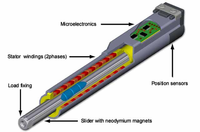
P linear motors consist of a slider and a stator. In the stator, the main
parts of the motor, including windings, bearings and sensors for position
detection and temperature monitoring, are integrated into a stable metal
cylinder. All elements are moulded into the stator and are therefore optimally
protected against damage and dirt. The slider consists of a stainless
steel tube in which the magnets are fitted. The sliders have a drilled
hole at each end with an inside thread for the attachment of loads. In
operation, the slider is guided by slide bearings integrated in the stator.
There are no electronic connections between stator and slider. Position
detection is done on a contact-free basis using magnetic field sensors
in the stator. The linear motors are delivered with a nine-pole cable
with an appropriate connector for connection to LinMot E servo controllers.
|
 |
| |
|
| Mode
of operation |
| LinMot
P linear motors are two-phase synchronous motors with permanent magnet-excitation,
integrated bearings, position sensors and temperature monitoring. Linear
motion is generated directly by electromechanical forces without any additional,
wear-prone mechanical elements. Extremely dynamic movement processes can
thus be implemented using LinMot P linear motors in the simplest possible
way and without the use of additional components. In the same way as in
rotating synchronous motors, permanent magnets are used in the slider (cf.
rotor) and windings in the stator to create force. Due to their special
construction and a different arrangement of the permanent magnets, the linear
motion is produced directly by electro-mechanical forces (see illustrations
a - c below). |
 |
| |
|
| Stroke
/ force characteristics |
| The
maximum force offered by a LinMot P linear motor is determined by its construction
and is dependent on the position of the slider in the stator. The maximum
force curve is symmetric to the centre of the movement range, the so-called
Zero Position ZP. If the distance between the end of the stator and the
end of the slider is equal to the Zero Position ZP of the motor, the slider
is at the centre of its movement range. The Zero Position ZP can be found
in the data sheet of each linear motor and is different for each motor.
In the SS (shortened stroke) range, the slider's drive magnets are wholely
inside the active part of the stator. This provides optimum force generation
and a constant maximum force over the whole SS- stroke range. The more the
slider moves away from the SS-stroke range, the fewer of its magnets are
in the active part of the stator. This means that the maximum and effective
forces are reduced linearly as the end of the stroke range S is approached. |
| |
 |
| |
|
 |
Further,
the maximum force is dependent on the supply voltage. In the stroke - force
diagram, the maximum force is shown for various supply voltages in dependence
of slider position.
Tip: Choose operational ranges to be symmetrical to the Zero Point ZP of
the motor, as the linear motor develops its greatest force in this area.
|
| |
|
| Stroke
- Time diagram |
| The
stroke-time diagram provides information on the minimum travelling times
for a horizontal point-to-point motion in dependence of varying load mass.
A sinusoidal motion is assumed. In the Position-Time diagram, all factors
influencing particular linear motors such as motor reverse voltage, slider
mass, or bearing friction are considered. The values shown in the diagram
cover the time taken from the definition of a new positional set-point up
to standstill at the target position. Should the travelling times read from
the diagrams be at the limit for a particular application or too short,
the actual performance should be ascertained by performing practical tests
in agreement with the supplier. Only in this manner can all application-specific
influencing factors (additional friction in bearings, thermal boundary conditions
etc.) be taken into account. If a linear motor is to move a load mass 45
mm, the time taken between the definition of the set-point and standstill
at the target position is, according to the example in the diagram, about
52 ms. |
 |
| |
|
| Limits
of performance and thermal behaviour |
| The
limit of performance of a linear motor is defined for short-time operation
by the maximum force and maximum speed of the slider alone. In cyclic operation
with sufficient standstill periods, these are the only factors that limit
performance. As soon as a constant force is to be provided and / or standstill
periods are not wanted, however, the continuous force of the linear motor
is the criterion for defining limits of performance. The continuous force
of a linear motor depends on the power dissipation and the maximum allowable
operating temperature. This is itself basically dependent on ambient temperature
and the cooling and mounting of the motor. The data sheets show the continuous
force of linear motors fitted with a standard flange and without additional
cooling. Using forced cooling of the linear motor with a ventilator the
continuous force available can be doubled. |
| |
|
| Behaviour
when overloaded or jammed |
| One
of the main advantages of LinMot P drives is that the motors are not subject
to damage when jammed by foreign bodies etc. pre-determined breaking points
or slip couplings are not necessary in such situations for the protection
of sensitive cog wheels, gearboxes and axles. When jams or overload occur,
LinMot?E servo controllers issue user-definable error signals, which can
be used by the overlaid controller to initiate appropriate action. Similarly,
thermal overload of the linear motors is detected and thus taken care of. |
| |
|
| Mounting
the linear motors |
| Linear
motors are mounted by clamping over the largest possible surface in the
stator's mounting zone. The size of the clamping surface, together with
the heat-sink capability of the motor mounting has a direct influence on
the loading capacity of the motor. Mounting flanges with the designation
"PF01" which guarantee optimum mounting are available for all motor types. |
| |
| Load
connection |
| The
sliders of the linear motors have at their ends boreholes with an inside
thread for the attachment of loads. When attaching the load, only that end
of the slider next to the load may be held by a spanner. Using a locating
hole, the end of the slider can be connected to the load by clamping (see
construction handbook). The stators of the linear motors are fitted with
integrated slide bearings. These are primarily designed as bearings for
the slider itself. The load must have external guides and thus it's own
bearings. When attaching loads, constructional care must be taken to prevent
over-defined bearings and to compensate for errors in parallelism (compensation
coupling, precise alignment of motors and external guides). Lateral forces
on the slider, which can occur when loads are improperly attached, lead
to a reduction of the service life of the linear motors. |
| |
|
| Power
supply voltage |
In
the tables on the LinMot P drives, technical data is specified for various
supply voltages. This information refers to the supply voltage of the LinMot
E servo controllers. Basically, a higher supply voltage offers higher peak
force and therefore a more dynamic operation of the drives. The maximum
continuous force is, however, limited by power dissipation and is not dependent
on supply voltage.
The LinMot P family of linear drives replace a large number of mechanical
components. |
 |
| |
|
| Product
lines and their designation |
LinMot?
P linear motors are available in four product lines P01-23x80, P01-23x120,
P01-37x120 and P01-23x240. The different product lines are primarily distinguished
by their different stroke ranges, maximum force and mechanical dimensions.
The stators are identical in any particular product line.
The following example shows how the designation scheme works: |
 |
The
P02 heavy-duty implementation has sliders whose surfaces are coated on a
titanium basis exhibiting a microhardness of 2300 HV 0.05. Design and mechanical
dimensions are identical with the P01 series.
The P02 series has the following advantages:
More resistant against dirt, especially when in contact with abrasive
materials.
Generally longer service life under critical conditions.
The use of the heavy-duty version is recommended when:
Drive servicing is difficult.
Working environment is dirty.
|
| |
|
| Forced
Cooling |
| The
continuous force of the linear motors is basically dependent on their cooling.
The values for continuous force quoted in the data sheets can be substantially
increased by forced cooling using a ventilator. If linear motors mounted
with a standard flange are additionally cooled by a ventilator, they can
be operated at double the continuous force in an air current of 2 m/s (see
data sheets). |
| |
|
| Initialisation |
| After
the servo controllers are switched on, positional initialisation has to
be acquired in the form of a homing run to find the zero position. The user
can configure the initialisation. The following initialisation modi are
available: |
Actual
position:
The actual position at the start of the initialisation
procedure is taken as being the zero position, without moving the slider.
|
|
Auto
move out:
The slider of the linear motor is moved out during initialisation
until a stop is reached. This position is set as the zero position.
|
Auto
move in:
The slider of the linear motor is moved inwards during
initialisation until a stop is reached. This position is set as the zero
position.
|
 |
 |
Trig
move in / trig move out
The slider of the linear motor is moved in or out until
the trigger signal of an external sensor goes from 0 to logical 1. The position
reached at the positive transition of the trigger signal is taken as the
zero point. |
Turn
left / turn right
The stepping motor turns
to the right or to the left until the trigger signal of an external sensor
goes from 0 to logical 1. The current position is taken as the zero point.
After the initialisation is completed, it can be checked if the slider of
the linear motor can be moved freely over the whole of the range of movement
necessary. Initialisation faults or jammed sections lead automatically to
the sending of appropriate error messages to the overlaid control system.
|
| |
|
| Motors
with Hollow Sliders |
Series
P01-37x120 and P01-37x240 linear motors are also available with hollow sliders.
These motors have a 6mm diameter concentric hole through the slider. In
this way, constructions for handling machines using pneumatic or vacuum
gripping devices can be realised in a minimum of space, whereby the linear
motor's hollow slider is used for the air or vacuum supply.
If electronic sensors or actors are moved together with the linear motor,
their cables can be fed through the slider and connected to the electronics.
Expensive and space-wasting constructions for cabling near to the moving
parts can thus be avoided. The motors do not differ in their external dimensions
from the standard types.
The following linear motors are available with hollow sliders:
| Designation |
Part
number |
| P01-37x120/20x100-L |
0150-1175 |
| P01-37x120/80x160-L |
0150-1176 |
| P01-37x120/180x260-L |
0150-1177 |
| P01-37x240/100x100-L |
0150-1178 |
| P01-37x240/40x160-L |
0150-1179 |
| P01-37x240/60x260-L |
0150-1180 |
|
 |
| |
|
| Environmental
Conditions |
The
stable stator housing, which contains all electronic components, allows
the linear motors to be used in raw environments. The magnetic measurement
system for position detection guarantees reliable operation even in very
dirty environments.
LinMot linear motors are waterproof and can be even used under water if
the appropriate connectors are used. Use in very moist environments, underwater
use or use in contact with aggressive fluids or gasses should only take
place after consultation with the supplier.
|
Several stators on the
same slider allow several independent linear motions in tight spaces. |
The sliders of long-stroke
motors protrude on both sides of the stator, which is open at both ends. |
| |
|
| Use
in Clean Rooms |
| The
certificate no. FM9805-3475 from the Fraunhofer Institute in Stuttgart attests
the suitability of the motors for use in class 1 clean rooms for speeds
of movement up to 0.45 m/s and class 10 for speeds of movement up to 1.2
m/s. Measurements were performed to US Fed. Standard 209E. |
 |
| |
|
| Motor
Selection Guide |
 |
| |